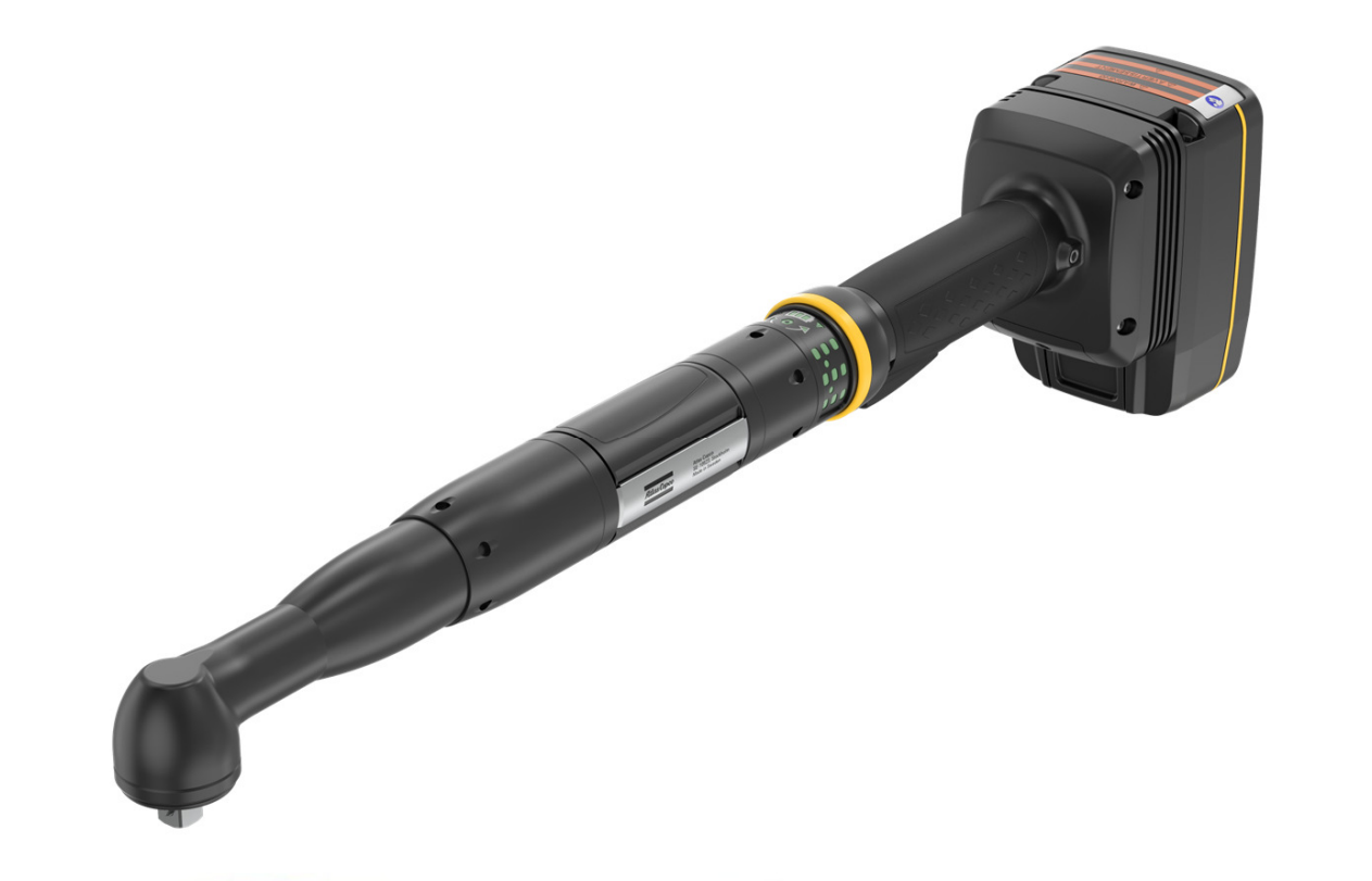
The Atlas Copco Tensor ITB-A61-50-10 gave us the product context. Our course model used a separately assigned Faulhaber 3268 036 BX4 motor, so what we built is a modelling method rather than a digital twin of the commercial tool. We built the analysis progressively, checking equivalent motor representations against each other before adding transmission and tightening behaviour.
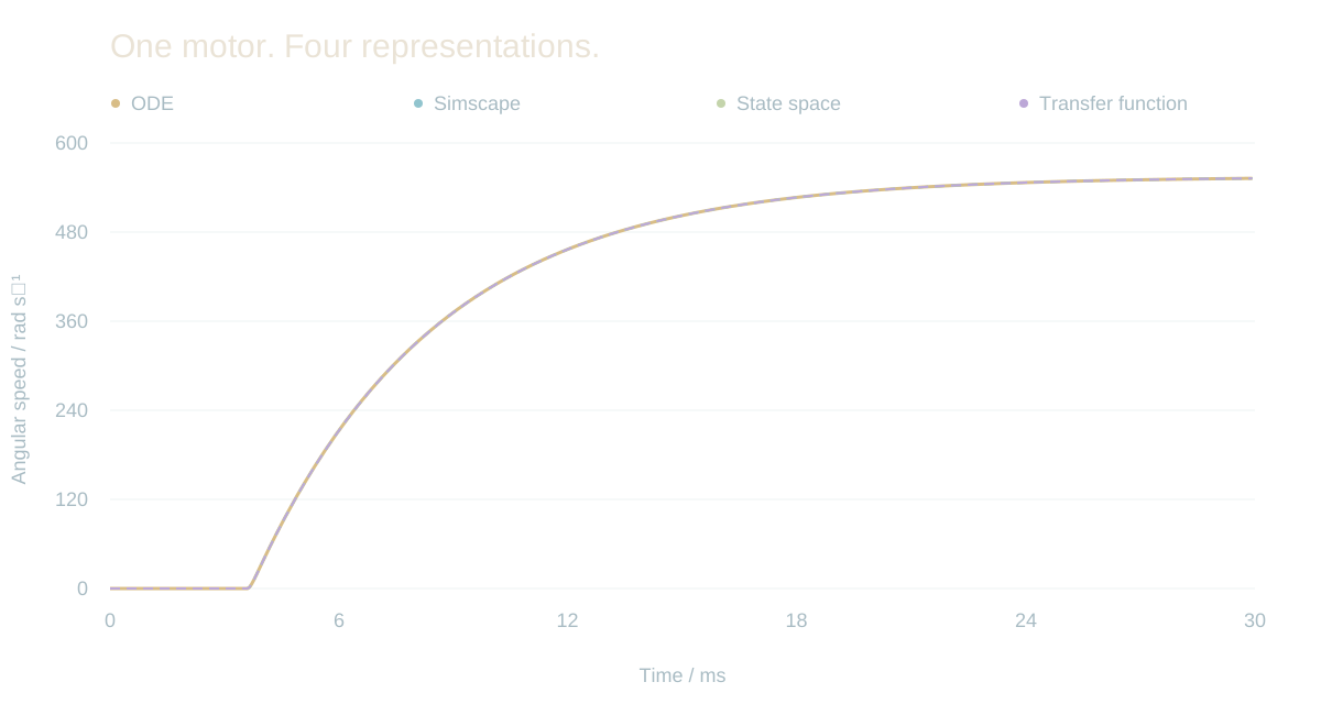
Recovered Task 2 Simulink traces, replotted without changing their values. Four representations of the same 36 V motor step.
01 / Establish the model
Different representations. The same response.
Electrical current produces motor torque; back EMF and mechanical damping shape the speed response. We described the same motor four ways: differential equations, a state-space model, a transfer function and a Simscape physical model. Agreement between independent formulations is what made the model trustworthy enough to build on.
The plot above comes from the original saved simulation signals. Their block paths identify each model, so the agreement can be inspected without relying on a screenshot of a plot.
ELECTRICAL
L di/dt = U − Ri − Kₑω
MECHANICAL
J dω/dt = Kₘi − bω
CHECK
A 36 V step across four implementations
Reference product versus assigned motor+
The commercial nutrunner and the simulated motor are not the same hardware. Report page 29 contrasts the assigned 62 W motor with the commercial tool’s 1,500 W motor. The study therefore demonstrates a modelling method, not a validated digital twin of the commercial nutrunner.
Source: MF2030 report, PDF pp6–14,29; motor_specs.m; task2PlotValues.mat.
02 / Add control, then simplify
Keep the dynamics that matter.
A PI controller regulates motor speed while respecting the model’s voltage and current limits. We used a 12 rad/s reference with gains P = 1.927 and I = 1, tuned experimentally against those limits.
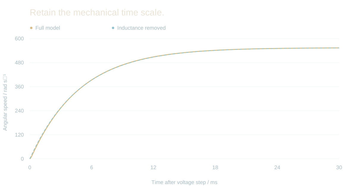
The electrical pole is much faster than the mechanical response, so we removed the inductance to obtain a simpler model for the system study. The comparison below is a new evaluation of the original full and reduced equations, prepared for this page.
New isolated Python evaluation of the original motor_specs.m full and reduced equations. This does not rerun the complete Simulink tightening model.
What has been recomputed+
For this page, the original saved Task 2 traces were independently decoded from MATLAB HDF5 signal streams. The motor response was checked against the exact state-space solution at those same timestamps, including the 3.6 ms input-step delay. The reduction plot is a separate isolated Python computation; the complete Simulink tightening model has not been rerun.
Source: Report PDF pp12–14,20–23; motor_specs.m; recovered Task 2–4 data.
03 / The transmission and joint
The motor turns. The joint responds.
A gear ratio alone is not enough to describe tightening. Transmission stiffness and damping separate motor motion from output motion, and our model then connects output rotation to the elastic extension of an M8 screw.
Rundown brings the fastener into contact; clamping builds force. Friction changes how much of the available torque becomes useful preload, which changes the result even at the same stopping threshold.
RUNDOWN
Speed-controlled approach
TRANSMISSION
Motor and output angles + speeds
CLAMPING
Elastic M8 screw model
STOP
Torque threshold ends tightening
Assumptions worth keeping visible+
Our model uses lumped stiffness and damping, a simplified screw model and selected friction assumptions. It does not include every gearbox loss, thread variation, temperature effect or physical tool behaviour. The report’s battery-use estimate is also a model-based estimate, not an endurance test.
Source: Report PDF pp15–19,23–29; original Task 5–9 model files.
04 / Read the consequence
Same cutoff torque. A different clamp force.
At a 25 N·m stopping threshold, the report compares 103.4 kN without Coulomb friction with 22.4 kN when μ = 0.2. That difference is the result I find most instructive: one modelling decision changes the predicted clamp force by a factor of more than four.
Use the comparison to inspect the reported cases. These values are simulation outputs with an assumed friction coefficient, not measured clamp forces.
103.4kN
Predicted clamp force 2.35 s to the 25 N·m cutoff
Reported simulation cases · comparison, not a live physical model
Additional reported cases+
With μ = 0.2, the report gives 19.1 kN at 22 N·m and 17.0 kN at 20 N·m. The corresponding tightening times are 0.480 s and 0.431 s. At 25 N·m the two compared times are 2.35 s without Coulomb friction and 0.552 s with it.
Source: Report PDF pp26–27, Tables 3–4.
Guided scroll · scroll or press Escape to take over