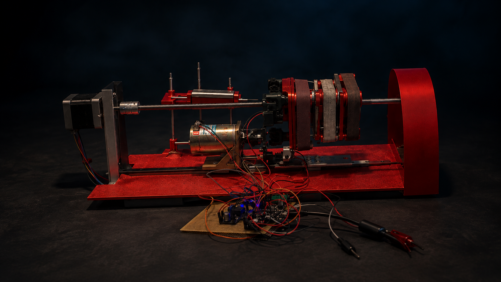
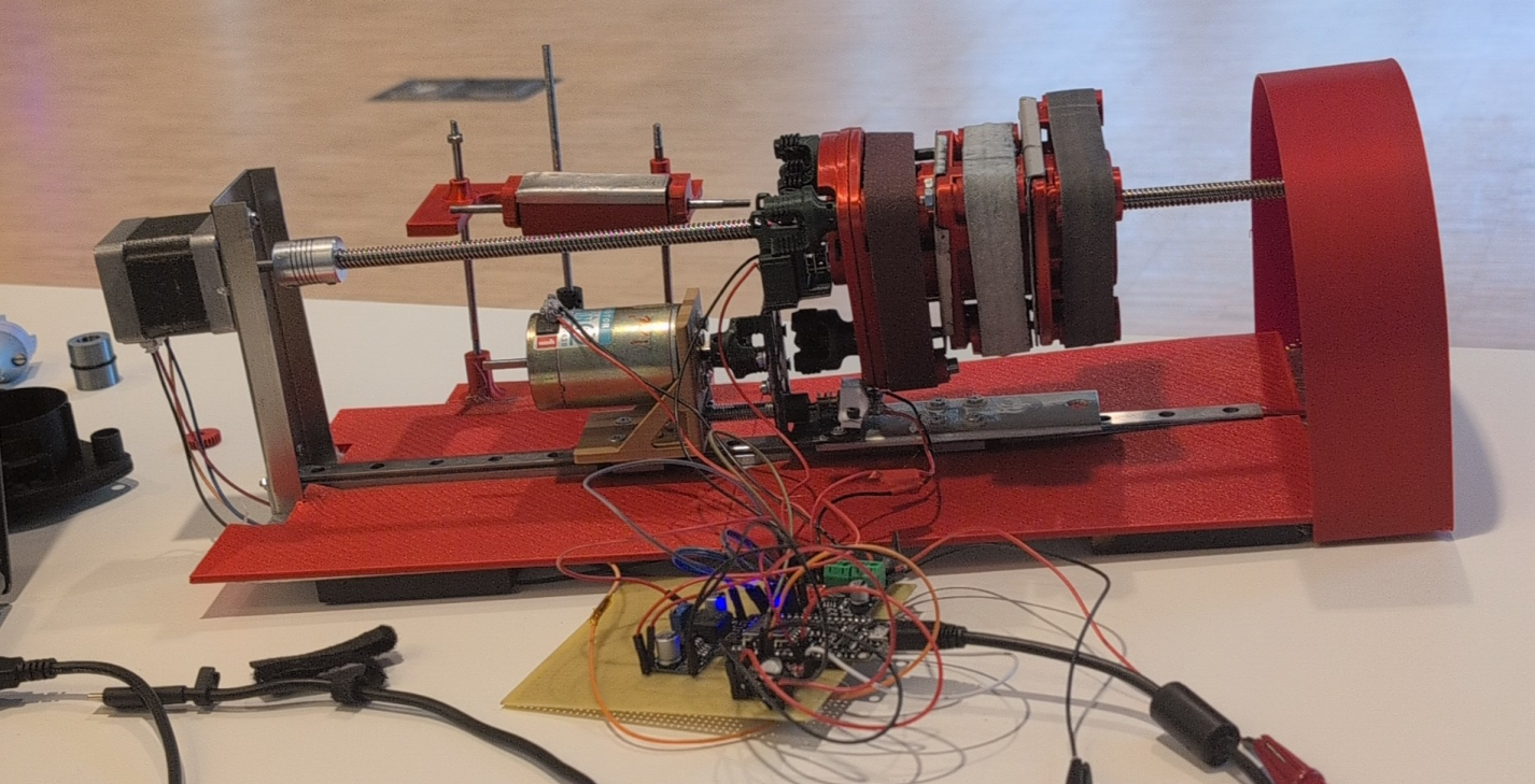
I set out to build a compact, affordable knife sharpener that could offer different levels of sharpness: sharp, sharper and sharpest was the range I had in mind, not a measured result. My design response was a multistage machine: three belts of different abrasive grades on a rotating, indexed carriage, sharing one abrasive drive, while the knife stays still and the carriage travels along its edge. The prototype demonstrated stage indexing, travel along the knife and supervised sharpening at a fixed angle. The knife holder was not finished to its intended design, and the AI-based edge tracking I had planned did not fit in the time available.
WITH
Lukas Fagerholm
WORK
Concept, CAD, printing and machining, electronics, embedded control
OUTCOME
Physical prototype · supervised sharpening
Sharpening preview from the workshop. Original recording, 00:00–00:04.
01 / Architecture
Separate the motions. Make them meet.
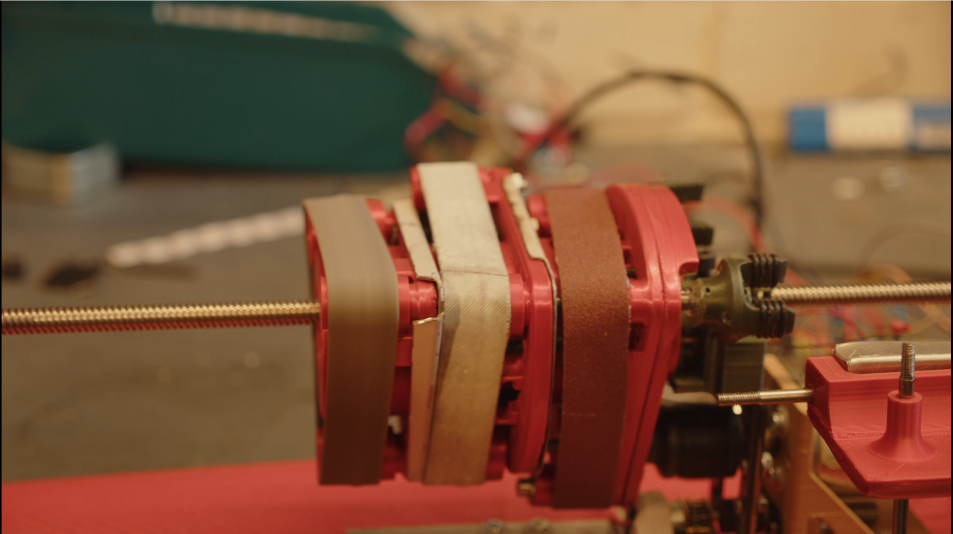
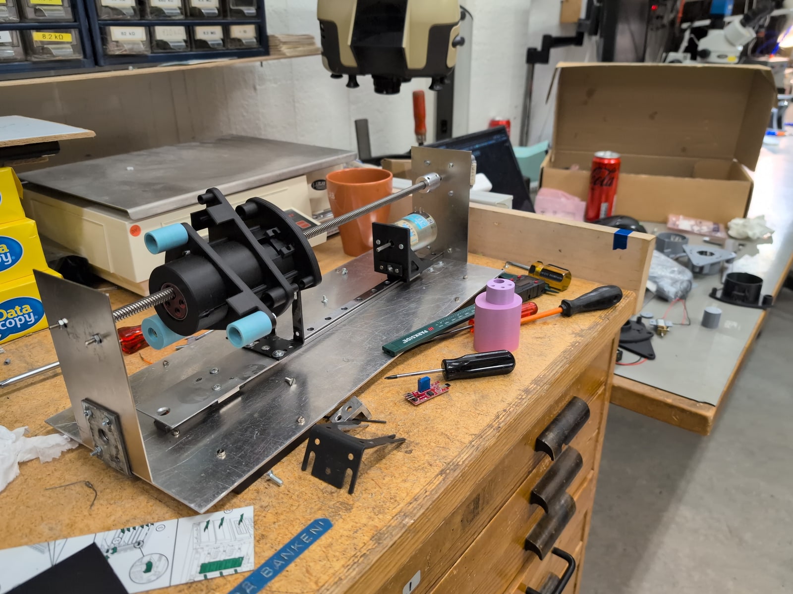
I gave each motion its own actuator so that I could build and test the functions one at a time. A NEMA 17 stepper turns a T8 lead screw and carries the sharpening head along a linear rail. A small geared N20 motor indexes the three-level gantry in 120° steps. A second screw-driven slide advances the belt-drive motor toward the shaft of the selected stage. Only the abrasive drive is shared: one Pittman DC motor serves all three belts instead of a high-speed motor riding on every level.
Separating the motions made each of them easier to test. Bringing them together made stiffness, alignment and access matter as much as the nominal CAD geometry.
The compact belts are approximately 19 × 305 mm. The feed screw has an 8 mm lead per revolution. These are design and command relationships, not measured positioning accuracy. I tested magnets and Hall-effect sensors as a way to confirm the stage position, but the final assembly still needed my judgement before the drive engaged.
Source: Final submitted thesis, PDF pp27–34.
02 / The drive interface
Less rotating mass. More exact alignment.
I kept the drive motor off the gantry so that no high-speed motor and its wiring had to rotate with the abrasive stages. The price is a mechanical handoff repeated at every stage change: the selected shaft and the motor must line up before the belt can start.
I designed the coupling as a dog-clutch-style positive interface and printed it in PETG with chamfered teeth, embedded repelling magnets and O-rings as compliant elements, so the two halves could find each other instead of colliding tooth on tooth. It engaged with assistance; repeatable unattended engagement remained a development task, and it taught me that minimising motors is not the same as minimising complexity.
The screw-driven motor slide approaches and withdraws from the coupling. Original presentation, 01:32–01:59.
Why the stopped state matters+
The intended sequence is stop, disengage, index, re-engage, then spin up. The coupler halves should meet at rest, because the impact energy of engaging with a speed difference grows with the square of that difference. A finished controller would enforce that condition from confirmed states; my prototype depended on supervision.
Source: Final submitted thesis, PDF pp31–32; original presentation 01:32–01:59.
03 / Iteration in the workshop
The drawing met the load.
The early one-belt test below uses a handheld drill to drive the belt, making the first sharpening trial visible before the integrated motor drive. Belt tension bent the printed gantry levels and tilted the pulley axes. I cut, drilled and bent metal reinforcement plates, designed crowned tracking pulleys and fitted O-rings to the drive pulleys, treating stiffness, tracking and traction as three separate problems.
An earlier fixed-cam tensioner that I tested on its own was not fully retained in the final demonstration. The knife holder followed a similar path: I built a fixed-angle clamp that closes the load path into the base, but the intended holder with angle and contact adjustment was never finished. The sharpening demonstrations used a hand-held knife, the intended holder remained unfinished, and stage changes still needed supervision.
An early one-belt sharpening test, driven with a handheld drill. Original recording, 00:29–00:38.
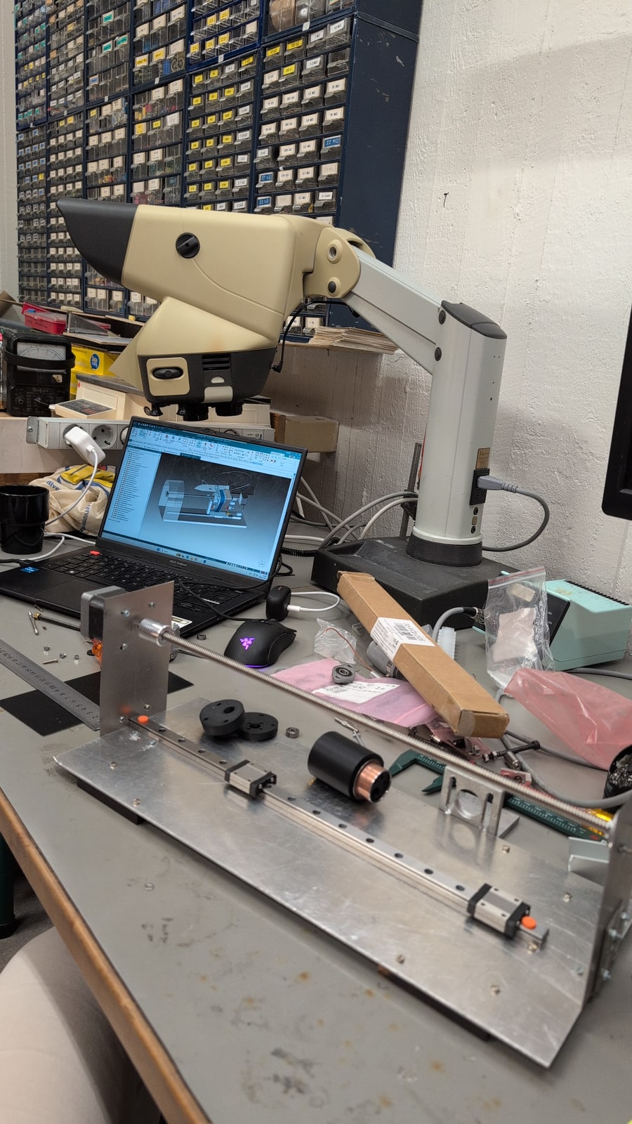
The gantry taking shape on the base, with printed parts and hand tools around the assembly.
Control and manufacture+
I printed the structural parts in PLA and the couplers in PETG, and did the drilling, cutting, filing, tapping and fitting by hand. I wrote the firmware for a NodeMCU-style ESP8266 that accepts serial commands from a browser console I made for the bench, driving one A4988 stepper channel for the feed and three DRV8871 DC channels for indexing, engagement and the belt drive. This was open-loop actuator control, without automatic force or angle adjustment.
Source: Final submitted thesis, PDF pp30–35; original first-run footage.
04 / Demonstrated, and still to develop
A working prototype. A measurable next step.
The machine demonstrated indexing between its three stages, carriage travel along the knife, a running belt and supervised sharpening at a fixed angle. The footage shows the work at the blade rather than asking a render to stand in for a test.
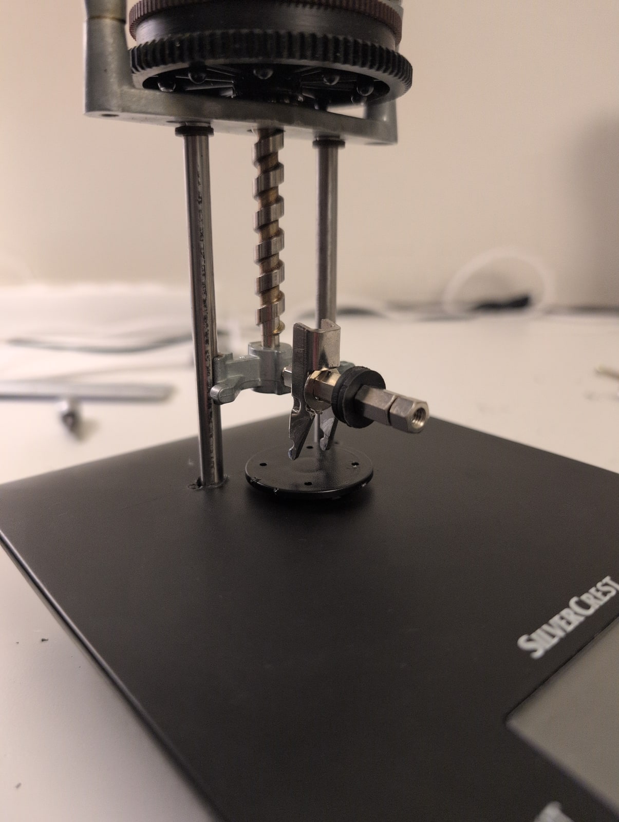
Alongside the unfinished holder, two other goals were not completed. The AI-based edge tracking I had planned, so the machine could follow and assess the edge on its own, stayed a separate image-processing experiment and never reached the controller. A force-to-cut rig for judging sharpness was assembled mechanically, but its measurement electronics were not calibrated. The project did not produce a quantified before/after sharpness dataset.
Supervised sharpening on the physical prototype. Original workshop recording, 00:37–00:42.
A closer look at the force-to-cut rig: screw feed, guides and clamp. The mechanism was assembled; calibrated measurement remained unfinished.
Outcome boundaries+
The fixed angle and the unfinished holder limited the range of knife geometries I could test. Belt speed, contact force and feed repeatability were not formally characterised. Reliable stage confirmation, engagement sensing, a finished holder with angle and contact adjustment, and calibrated edge assessment are the next validation tasks.
Source: Final submitted thesis, PDF pp36–42; original workshop footage 00:37–00:42.
Guided scroll · scroll or press Escape to take over