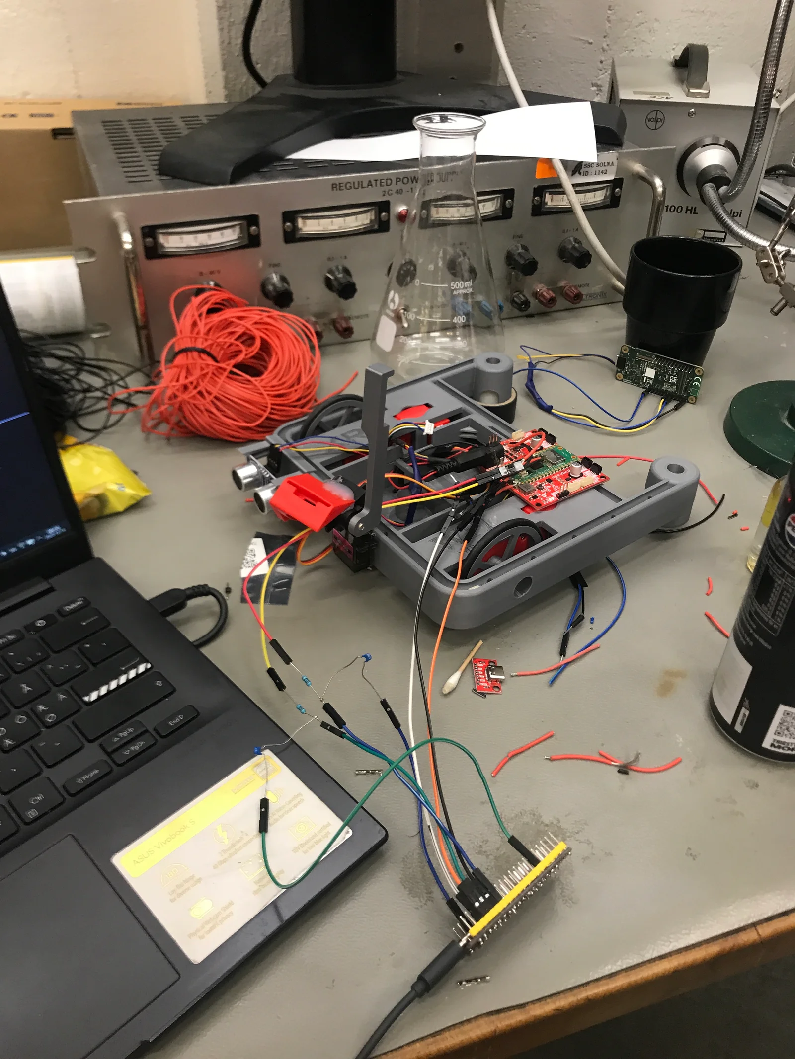
We coupled a Coral vision board to an XRP robot controller so that what the camera sees could decide what the robot does next. Detection labels feed a state machine: follow the line, recognise a plate, search for a bucket, attempt the pickup and find the exit arrow. My own work ran through the perception data, the controller logic and the debugging of the link between the two boards, and this page is honest about which of those were validated.
WORK
Training data · embedded inference · robot state machine
PLATFORM
Coral vision system + XRP controller
OUTCOME
Development and partial integration
A handheld look at the camera assembly, wiring and robot during bench development. Original recording, 00:00–00:11.4.
01 / The view from the robot
Learn the objects in their environment.
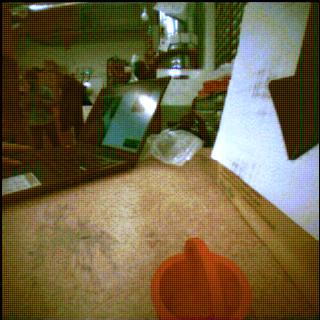
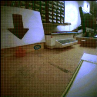
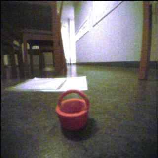
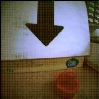
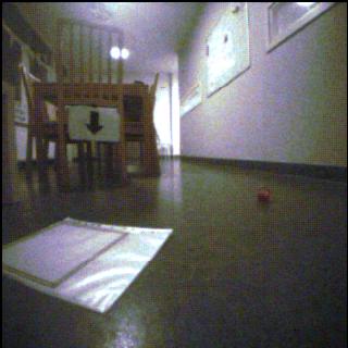
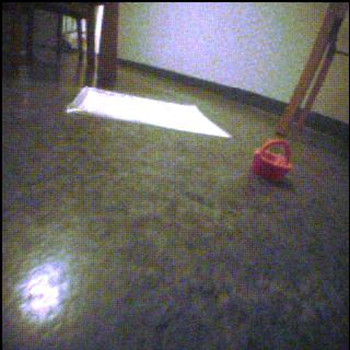
The training images came from the robot’s own camera in the actual room: floor reflections, changing object scale and the same objects seen from different positions. Those conditions are part of the perception problem the detector had to learn.
The detector uses four labels: arrow, picked-up bucket, bucket and plate. The images on this page are samples from that source dataset. I have not added detection boxes or confidence scores, because the record contains no measured detector output to show.
Original 320 × 320 training-camera sample. No detection output is overlaid.
What this material establishes+
The recovered material includes camera images, model-export folders and robot-control modules. It establishes dataset and implementation work. It does not, by itself, establish held-out detector accuracy, real-time latency or a successful complete mission.
Source: Original Drive dataset samples; project README and robot_control modules.
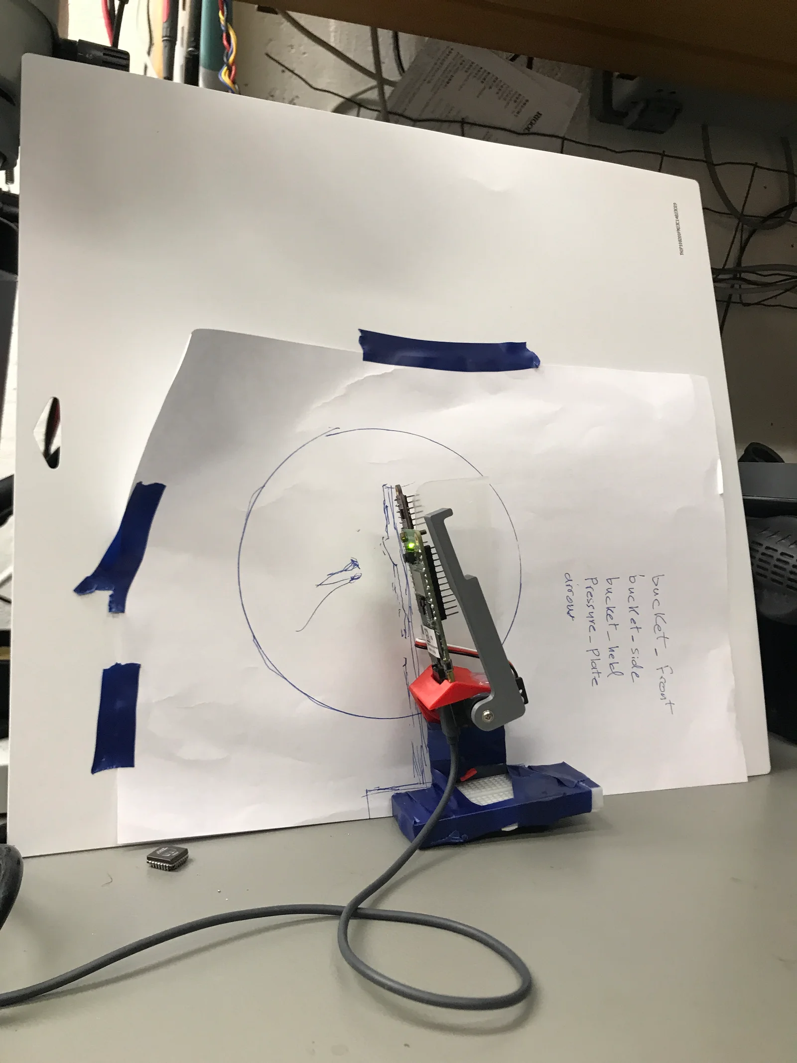
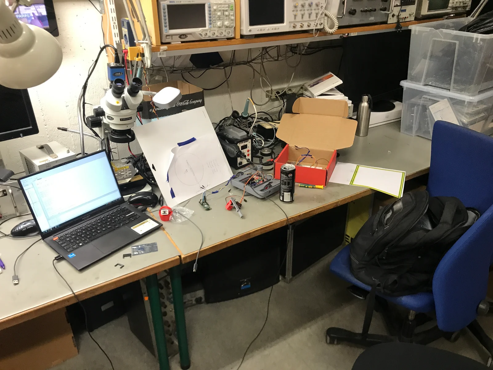
The camera board and mount on a bench fixture, beside handwritten object labels.
02 / The mission logic
A detection is useful when it changes a decision.
Our controller looks for fresh detections, uses object position and apparent width during an approach, and combines vision with line, wall and encoder information. I wanted those responsibilities explicit rather than buried in one loop, so the mission is a state machine with named states and transitions.
The course mission supplies the order. Our implementation supplies the transitions, the motor actions and the fallback behaviour. The sequence below explains that logic; it is not a replay of a successful robot run.
01 · PLATE
Find the plate and wait
02 · BUCKET
Explore, centre and approach
03 · PICKUP
Lower, advance and grab
04 · EXIT
Search for the arrow and return to the line
A specific integration gap+
In the recovered pickup handler, LABEL_PICKED is checked and a success or warning message is printed. Both branches then move to BACK_FROM_BUCKET, so pickup confirmation does not yet gate mission continuation. I have left that as the record shows it: a robust sequence needs a confirmed or explicitly handled pickup outcome, and we did not get there.
Source: state_machine.py, _step_pickup and _step_back_from_bucket; MF2143 assignment.
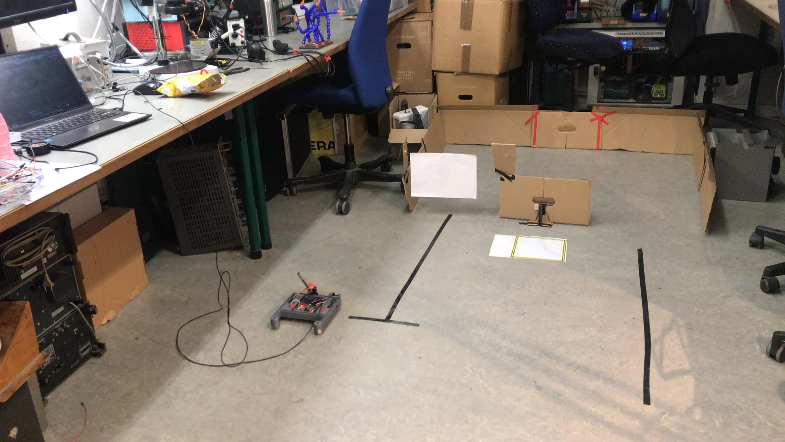
The physical test course, with floor tape, cardboard boundaries and the robot.
A fallback input / Bench test
Another way to give a command.
I also explored keyword spotting as a fallback input for the XRP project. This recording shows that test with an on-screen maze providing feedback while I work with the board at the bench.
It documents the fallback experiment separately from the camera-driven mission. The recording does not establish recognition accuracy or completion of the robot mission. Original sound is available through the player controls.
Keyword-spotting fallback testing for the XRP project, using an on-screen maze for feedback. Identified by Aladdin; original recording, 00:06–00:36, with sound.
03 / Between two boards
Perception and motion need a dependable conversation.
Most of my debugging went into the link between the two boards. The robot’s USB port was damaged, so I flashed the controller over SWD through a second Pico set up as a debug probe, which became our recovery route, and moved the serial console off the noisy default pins to a second UART.
The return channel from the robot to the Coral board arrived garbled. My working hypothesis is that the Coral’s UART clock, derived from an RC oscillator, drifts enough at 115200 baud to break framing after a few characters; a lower rate helped without curing it, and the measurements that would settle it are still open. The README and code comments disagree about which UART direction was working. Reliable communication in both directions remains unresolved in the project record.
CORAL
Camera input and object detections
SERIAL LINK
Message format, timing and reception
XRP
State transitions, drive and pickup control
Current presentation scope+
The evidence I can show includes the camera dataset, controller implementation, prototype photographs, bench footage and a separate keyword-spotting fallback test. Reliable two-way communication, confirmed pickup and a complete autonomous mission remain unvalidated. The reviewed record does not establish detector accuracy or inference latency.
Source: README, ISSUES and coral.py; controller source; Canvas project requirements.